


The use of Time of Flight (ToF) laser rangefinder sensors to monitor the combustion bed in a granular furnace is a technical solution that obtains real-time combustion bed status (such as height, flatness, material distribution, etc.) through non-contact means. It can be used to optimize combustion efficiency, prevent coking or material blockage, and other issues. The following are specific implementation ideas, key technical points, and precautions:
1、 Monitoring objectives and core requirements
The combustion bed of a pellet furnace (such as a biomass pellet furnace) is the area where fuel (pellet biomass) is burned, and its state directly affects the combustion efficiency:
Burning bed heightExcessive levels may lead to insufficient oxygen supply and incomplete combustion; Too low may result in unstable heat output.
Surface FlatnessLocal accumulation or depression may cause local high temperature (coking) or flameout.
Material consumption rateReal time monitoring can be linked to the feeding system to achieve automatic feeding.
The core function of ToF sensors isReal time measurement of the distance between the combustion bed surface and the sensorIndirectly reflecting the above state.
2、 Key points for selecting ToF laser ranging sensors
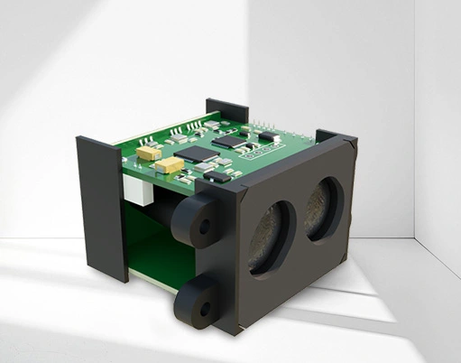
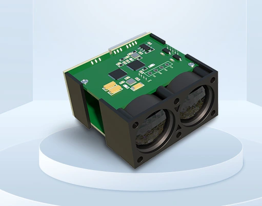
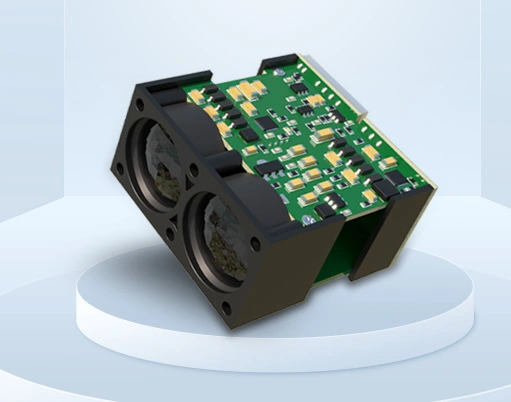
Suitable sensors need to be selected for the harsh environment of the pellet furnace (high temperature, dust, water vapor, vibration):1. measuring range
The installation distance between the pellet furnace combustion bed and the sensor is usually 0.3~2 meters, and sensors with a range coverage of 0.1~5 meters can be selected (such as VL53L5, TFmini-S, etc.).
2. Accuracy and Resolution
It is necessary to distinguish the height variation of the combustion bed surface from 1 to 5mm, and select a model with an accuracy of ≤± 3mm and a resolution of ≥ 1mm (to avoid measurement fluctuations caused by particle gaps).
3. anti-interference ability
Anti dustThe smoke and dust generated during the combustion process will scatter the laser, so it is preferred to chooseLarge spot diameter(such as 1mm or more) orEquipped with anti-interference algorithmA sensor that takes the average of multiple measurements.
high temperature resistanceThe sensor body should be kept away from the combustion zone (ambient temperature ≤ 60 ℃), or cooled down through a heat dissipation bracket or cooling air duct; Some industrial grade sensors, such as the Sick TIM series, can withstand environments of -40~85 ℃.
Anti background lightThe strong light from burning flames may interfere with the receiving end, chooseEquipped with narrowband filterA sensor that only transmits laser wavelengths, such as 940nm infrared.
4. response speed
The state of the combustion bed changes slowly (in minutes), and a sampling rate of 1-10Hz can be selected to avoid data redundancy.
5. output interface
Prioritize UART (serial port) or I2C interface for easy connection with microcontrollers (such as Arduino, STM32) or PLCs to achieve data transmission and control.
3、 Installation and layout design
1. Installation position
The sensor should be directly facing the surface of the combustion bed to avoid tilting and causing the measurement distance to be too large (geometric correction is required to compensate for the tilt angle).
Stay away from the inlet and outlet to prevent material splashing or dust from directly covering the sensor lens.
Lens needs to be installedHigh temperature resistant dust cover(such as quartz glass cover), regularly clean (can be combined with automatic blowing device).
2. Multi sensor linkage (optional)
If the combustion bed area is large (such as an industrial pellet furnace) and a single sensor cannot cover the entire area, 2-3 sensors can be installed at different positions to calculate the overall flatness of the combustion bed (such as the highest/lowest difference and average height) through data fusion.
4、 Data Processing and Application Logic
1. Preprocessing of raw data
Filter out outliers: Occasional sparks or dust clusters during the combustion process may cause measurement values to jump. Outliers can be removed through "median filtering" or "sliding average filtering" (if the deviation of three consecutive measurements exceeds 10mm, they will be discarded).
Temperature compensation: The measurement accuracy of some sensors (such as VL6180X) is affected by the ambient temperature, and additional temperature sensors need to be used to collect the ambient temperature and correct the measurement value in the software.
2. State judgment and control logic
feed controlWhen the measured distance exceeds the set threshold for 5 consecutive seconds (such as when the height of the combustion bed is below 50mm), the feeding motor is triggered to work until the distance returns to the normal range (such as 80-100mm).
Dust removal reminderIf the height of the combustion bed continues to rise (possibly due to coking or ash accumulation) and exceeds the upper threshold (such as 150mm), users will be reminded to clear the ash through a buzzer or app push.
combustion optimizationCombined with the fan speed, when the surface flatness deviation of the combustion bed is too large (such as the maximum and minimum difference>30mm), adjust the fan speed distribution to reduce local high temperatures.
5、 Typical solution example (hardware+software)
Hardware composition
ToF sensor: TFmini-S (range 0.1~12m, accuracy ± 2cm, serial output)
Controller: STM32F103C8T6 (processing data, controlling peripherals)
Auxiliary sensor: DS18B20 (environmental temperature monitoring, used for temperature compensation)
Execution mechanism: feeding motor (stepper motor), cleaning push rod, buzzer
Power supply: 12V DC power supply (supplying power to sensors and motors, converted to 3.3V through DC-DC module for controller)
Software Process
Sensor initialization: Set the sampling rate of TFmini-S to 5Hz and read distance data through the serial port.
Data filtering: Take the average of 10 consecutive measurements and filter out outliers.
Temperature compensation: Based on the temperature value of DS18B20, call the preset compensation formula (such as distance correction+0.5mm for every 10 ℃ increase in temperature).
Status judgment:
If the compensated distance is greater than 150mm, trigger a dust removal reminder.
If the distance is less than 50mm, start the feeding motor until the distance is ≥ 80mm.
Calculate the standard deviation of 5 consecutive measurements, and if it is greater than 10mm, adjust the fan speed.
Data upload: Real time distance and status are sent to the upper computer or mobile app through a Bluetooth module (such as HC-05).
6、 Precautions
1. Lens cleaningThe tar and dust generated by combustion will adhere to the lens, causing measurement failure. It is necessary to regularly wipe it with an alcohol swab or design an automatic brush cleaning mechanism.2. LASERChoose Class 1 laser sensor (eye safety level) to avoid direct exposure to the human body.3. Anti vibrationDuring the operation of the pellet furnace, there may be vibrations, and the sensor needs to be fixed with an anti vibration bracket to reduce measurement errors caused by displacement.4. Calibration and CalibrationAfter installation, it is necessary to manually measure the actual distance from the sensor to the combustion bed, compare it with the sensor reading, and calibrate the deviation through software (such as adding a fixed compensation value).
By using ToF laser ranging sensors to monitor the combustion bed of particle furnaces, intelligent control can be achieved, improving combustion efficiency by about 10% to 20% while reducing manual maintenance frequency, making it suitable for upgrading and renovating household and small to medium-sized industrial particle furnaces.


