Proper installation is a critical determinant of the performance, accuracy, and longevity of a laser displacement sensor. This guide outlines the fundamental principles and best practices to ensure optimal results from the initial setup.
The first and most crucial step is selecting the correct mounting location. The sensor must be fixed to a stable, vibration-free structure. Even minor vibrations or movements in the mounting platform can introduce significant noise and error into the measurement data. Using a sturdy bracket or a dedicated sensor mount is highly recommended. The mounting surface should be rigid, and the fastener (typically a screw) should be tightened to the manufacturer's specified torque to prevent loosening over time.
Environmental factors play a paramount role. The sensor's optical window must be kept clean and free from obstructions. The installation site should be evaluated for ambient light interference, especially from strong direct sunlight or other high-intensity light sources, which can saturate the sensor's receiver. If operating in such conditions, consider using a protective shroud or housing. Additionally, the area should be free from excessive dust, oil mist, or steam, as particulate matter can scatter or block the laser beam. For harsh industrial environments, sensors with appropriate IP (Ingress Protection) ratings should be selected and installed with additional protective measures if necessary.
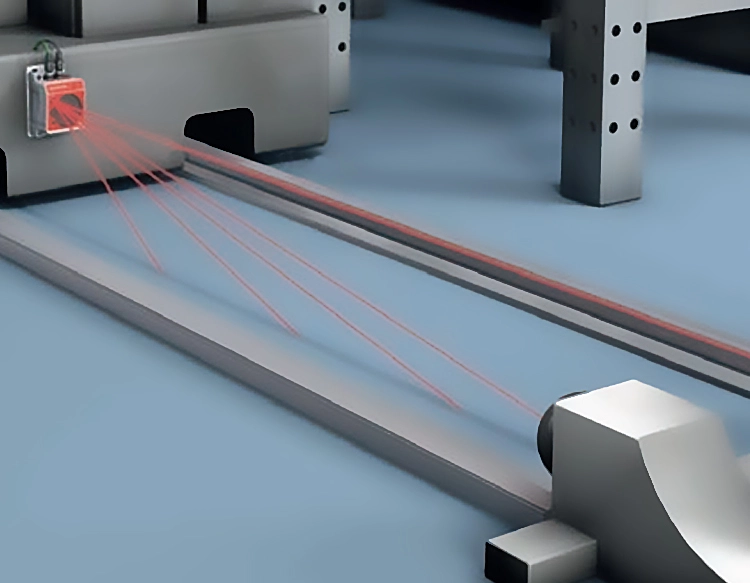
Alignment is the cornerstone of accurate measurement. The sensor must be positioned so that the laser beam is perpendicular to the target surface at the intended measurement point. Angular misalignment, where the beam strikes the target at an angle, causes cosine error, leading to a measured distance that is longer than the actual perpendicular distance. Most sensors have a built-in alignment aid, such as a visible red pilot laser or through-lens sight. Use these tools meticulously to ensure the laser dot is centered on the desired measurement area. For curved or uneven surfaces, the optimal point of perpendicular incidence must be carefully determined.
Electrical connections require careful attention to prevent noise and ensure safety. Always follow the wiring diagram provided in the sensor's datasheet. Use shielded cables and connect the shield to ground at the controller or power supply end to minimize electromagnetic interference (EMI). Ensure power supply specifications (voltage, current) match the sensor's requirements. For sensors with analog outputs (e.g., 4-20mA, 0-10V), verify the load impedance is within the specified range. For digital interfaces (e.g., RS-485, Ethernet), adhere to proper network termination and cabling standards. All connections should be secure; consider using crimped or soldered connectors for reliability.
Parameter configuration is not strictly part of physical installation but is essential for immediate functionality. After mounting and wiring, power on the sensor and connect to its configuration software or teach-in interface. Key parameters to set include the measurement range window, output scaling, response time/filter settings, and any triggering modes. Calibrating the output to the actual physical displacement using a known reference (like gauge blocks) is a recommended practice to verify system accuracy post-installation.
Finally, conduct a comprehensive validation test. Measure a known stationary target at different points within the working range to check for linearity and repeatability. Then, introduce the actual target under expected operating conditions—including its typical surface finish, color, and speed of movement—to ensure stable and reliable readings. Document all installation parameters, including mounting position, cable routing, and configuration settings, for future maintenance or troubleshooting reference. A meticulously planned and executed installation mitigates common issues, maximizes sensor capability, and forms the foundation for precise and dependable displacement measurement.


 +40729977919
  keysensor.ro@gmail.com