Optical sensors have become essential components in modern electronics projects, offering precise detection capabilities for light, color, proximity, and motion. When combined with Arduino, these sensors open up a world of possibilities for hobbyists, students, and professionals alike. This guide explores the fundamentals of using optical sensors with Arduino, providing practical insights for successful implementation.
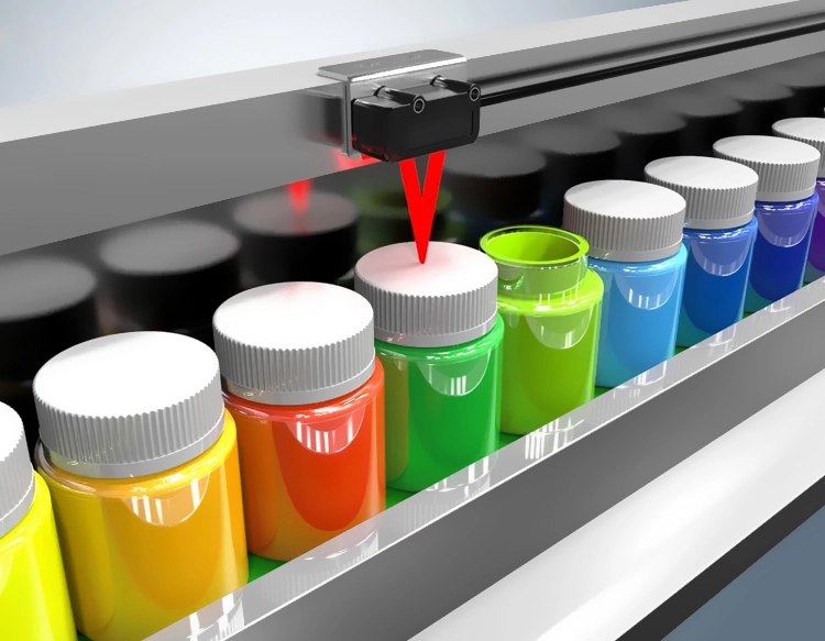
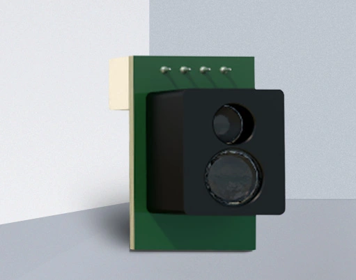
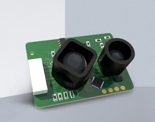
Arduino boards, known for their user-friendly interface and extensive community support, serve as ideal platforms for integrating optical sensors. Common types include photoresistors (LDRs), infrared (IR) sensors, color sensors, and laser modules. Each type operates on distinct principles. For instance, photoresistors change resistance based on light intensity, while IR sensors detect infrared radiation, often used in obstacle avoidance or remote control systems. Color sensors like the TCS34725 can identify RGB values, enabling applications in sorting or environmental monitoring.
To get started, users need basic components: an Arduino board (such as Uno or Nano), the optical sensor of choice, jumper wires, and a breadboard. Wiring typically involves connecting the sensor's VCC and GND pins to Arduino's 5V and ground, respectively, while signal pins link to analog or digital inputs. For example, a photoresistor might connect via a voltage divider circuit to an analog pin, allowing Arduino to read varying voltage levels as light changes.
Programming optical sensors with Arduino relies on the Arduino IDE and relevant libraries. Code often begins with initializing pins and serial communication. A simple sketch for a photoresistor could read analog values and print them to the serial monitor, helping users calibrate thresholds for light detection. More advanced projects, like using an IR sensor for object detection, might involve interrupts or dedicated libraries such as IRremote for decoding signals.
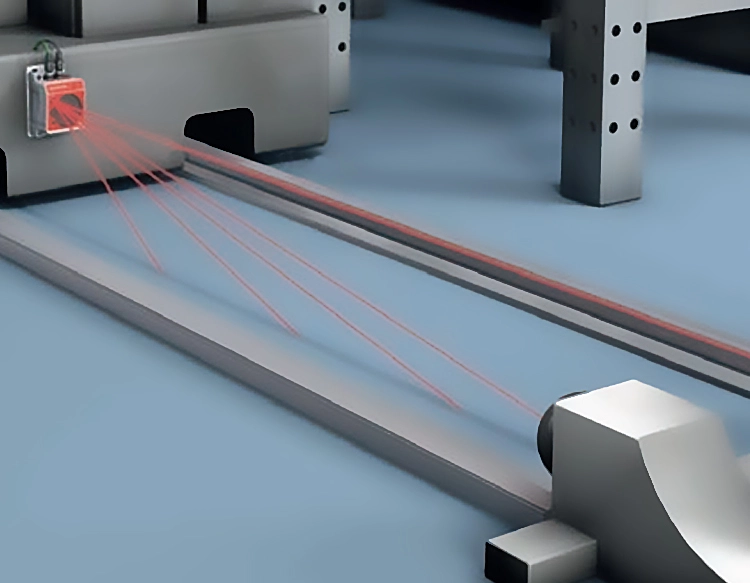
Practical applications abound. In home automation, optical sensors can adjust lighting based on ambient conditions or trigger security alarms upon detecting movement. Educational projects might include building a line-following robot with IR sensors or a color-sorting machine for STEM demonstrations. Environmental monitoring systems can use light sensors to track sunlight exposure for plants, while artistic installations might incorporate lasers for interactive displays.
Best practices ensure reliable results. Always refer to sensor datasheets for voltage requirements and pin configurations to prevent damage. Use pull-up or pull-down resistors where needed to stabilize signals. Calibration is crucial—test sensors under different conditions to set accurate thresholds. For instance, a proximity sensor might require adjusting the detection range to avoid false triggers. Additionally, consider power management; some sensors draw significant current, so external power supplies may be necessary for larger setups.
Troubleshooting common issues involves checking connections, verifying code syntax, and ensuring library compatibility. If a sensor returns erratic readings, noise filtering techniques like averaging multiple samples can improve accuracy. Community forums and Arduino's official documentation offer valuable resources for debugging.
In summary, Arduino optical sensors provide a versatile toolkit for innovative projects. By understanding their operation, wiring, and programming, users can harness light-based detection to create smart, responsive systems. Whether for simple experiments or complex prototypes, this combination empowers creativity in the digital age.


 +40729977919
  keysensor.ro@gmail.com