Fiber optic sensors represent a significant advancement in measurement technology, offering distinct advantages over traditional electronic sensors. When combined with Arduino, an accessible open-source electronics platform, these sensors become powerful tools for hobbyists, students, and engineers. This guide explores the fundamentals of integrating fiber optic sensors with Arduino boards for various sensing applications.
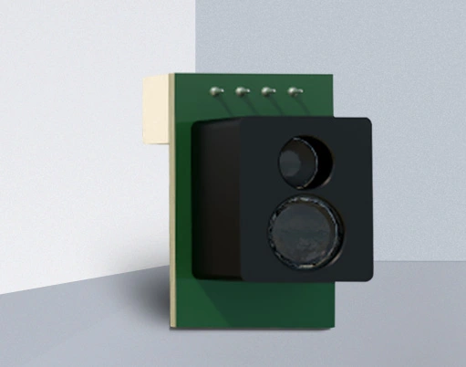
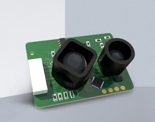
At its core, a fiber optic sensor uses optical fibers to transmit light. Changes in the light signal—such as intensity, phase, or wavelength—are used to detect environmental variables like temperature, pressure, strain, or chemical presence. The key components include a light source (often an LED or laser diode), the optical fiber itself, a sensing element or region, and a photodetector to convert the light signal back into an electrical one. This electrical signal is what an Arduino microcontroller can read and process.
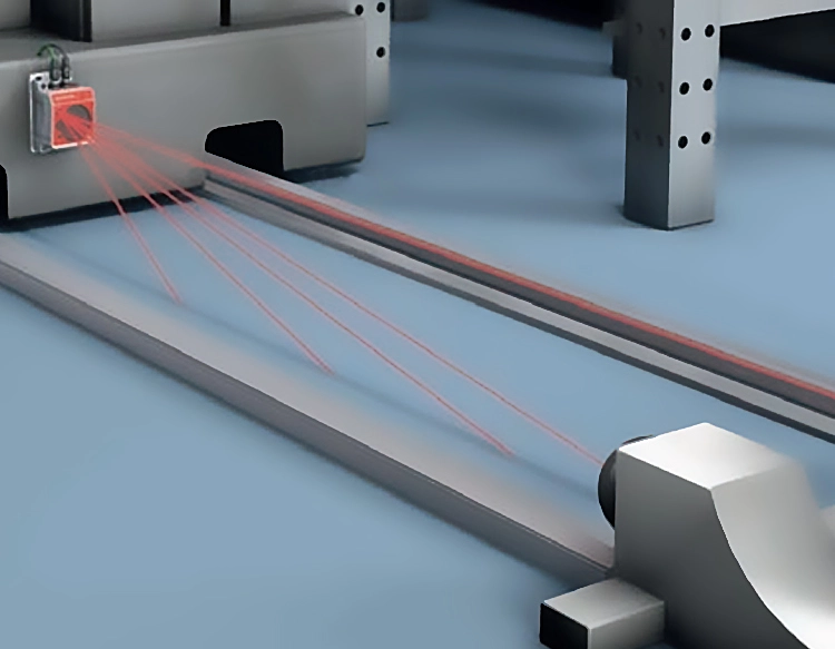
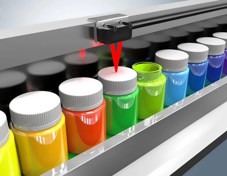
Arduino boards, particularly the popular Uno or Nano models, are ideal for this integration due to their analog input pins and programmability. A basic setup involves connecting the output of the fiber optic sensor's photodetector circuit to an Arduino analog pin. For instance, a simple intensity-based sensor might use an LED to send light through a fiber. When the light path is disturbed (e.g., by a moving object breaking the beam or by microbending in the fiber), the intensity at the photodetector changes. This change alters the voltage read by the Arduino, which can be calibrated to a physical measurement.
The process begins with hardware assembly. You will need an Arduino board, a compatible fiber optic sensor module (or components to build one: an LED, phototransistor, and fiber optic cables), jumper wires, and a breadboard. Many starter kits include reflective or through-beam sensor modules that are fiber-ready. Carefully connect the sensor's VCC and GND to the Arduino's 5V and GND pins. Then, connect the sensor's signal output wire to an analog input pin, such as A0.
Next, programming the Arduino is straightforward using the Arduino IDE. The code's primary function is to read the analog voltage from the sensor pin, often using theanalogRead() function. This raw value, typically between 0 and 1023, can be mapped to a useful unit or used to trigger actions. For example, a basic sketch might monitor the value and send a serial alert when it drops below a threshold, indicating an object has interrupted the light path. More advanced applications involve averaging readings for stability or implementing digital filtering to reduce noise.
Practical applications for an Arduino fiber optic sensor system are vast. In home projects, they can be used for secure, non-electrical door alarms, liquid level detection in tanks, or precise tachometers measuring rotational speed. In educational settings, they demonstrate principles of optics and transduction. For industrial prototyping, their immunity to electromagnetic interference (EMI) makes them suitable for use near motors or high-voltage equipment where traditional sensors might fail. They are also inherently safe in explosive or flammable environments as they do not generate sparks.
When developing your project, consider key factors for optimal performance. Choose the right type of fiber (plastic optical fiber is common for beginners due to its low cost and ease of handling). Ensure all optical connections are clean and secure to minimize signal loss. Calibration is crucial; characterize the sensor's response by taking readings under known conditions. Power supply stability is also vital, as fluctuations can affect the light source and detector readings.
Troubleshooting common issues often involves checking connections and light levels. If the Arduino reads a constant high or low value, verify the sensor is properly powered and that light is indeed traveling through the fiber. Use the Arduino's serial monitor to output raw analog values and observe changes when you interact with the sensor. Shielding the photodetector from ambient light is frequently necessary to prevent false readings.
The fusion of fiber optic sensing and Arduino opens a realm of precise, robust, and innovative measurement solutions. By starting with simple intensity-modulated sensors, users can grasp the core concepts before exploring more complex types like Fabry-Perot or Bragg grating sensors. This hands-on approach demystifies advanced optical technology, making it accessible for prototyping, learning, and solving real-world measurement challenges with a reliable, interference-resistant system. Continued experimentation and community-shared projects further expand the possibilities of this powerful combination.


 +40729977919
  keysensor.ro@gmail.com