Fiber optic sensors represent a significant advancement in sensing technology, offering unique advantages over traditional electronic sensors. When combined with Arduino, an accessible open-source electronics platform, these sensors become powerful tools for hobbyists, students, and engineers. This guide explains the fundamentals and provides practical knowledge for getting started.
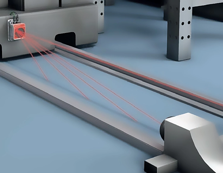
A fiber optic sensor typically uses an optical fiber as the sensing element. Light is transmitted through the fiber from a source, such as an LED. Changes in the light's properties—like intensity, phase, or wavelength—occur when the fiber interacts with the parameter being measured, such as pressure, temperature, or strain. A photodetector at the other end converts this altered light back into an electrical signal. The core principle is that external influences modulate the light traveling within the fiber.
Arduino interfaces seamlessly with this system. It can control the light source and read the output from the photodetector, which is often a simple photoresistor or photodiode connected to an analog pin. For instance, a basic intensity-modulated sensor can be built using an LED, a plastic optical fiber, and a photoresistor. Bending or applying pressure to the fiber causes light loss (attenuation), which the photoresistor detects as a change in resistance. The Arduino's analog-to-digital converter reads this change, allowing you to monitor and respond to it in your code.
The benefits of using fiber optics with Arduino are compelling. They are immune to electromagnetic interference (EMI), making them ideal for noisy industrial environments or near high-voltage equipment. The sensors are often small, lightweight, and can be used in harsh conditions where electronics might fail. Furthermore, they provide electrical isolation, enhancing safety when measuring parameters in hazardous or wet locations.
To build a simple demonstration project, you will need an Arduino board (Uno or Nano), an LED, a photoresistor, a length of plastic optical fiber (1-2 mm diameter works well), resistors, and jumper wires. Connect the LED to a digital pin through a current-limiting resistor. Connect the photoresistor in a voltage divider configuration to an analog input pin. Align one end of the fiber with the LED and the other end with the photoresistor, using heat-shrink tubing or black tape to block ambient light. In the Arduino IDE, write code to turn on the LED and continuously read the analog value. By bending the fiber, you will observe the analog reading change, confirming sensor operation.
Potential applications are vast. In home automation, such a sensor could act as a non-contact door or window sensor. In DIY projects, it could measure tiny displacements or vibrations. For educational purposes, it perfectly illustrates the principles of optics and transduction. More advanced setups could involve multiple sensors or different types of modulation.
However, beginners should be aware of challenges. Precise alignment of the fiber with the light source and detector is crucial for consistent readings. Ambient light must be shielded effectively. Plastic optical fibers are affordable and easy to handle but have higher attenuation than glass fibers, limiting transmission distance for simple setups. Calibration is necessary to map the analog readings to physical quantities.
In conclusion, integrating a fiber optic sensor with Arduino opens a world of precise, robust, and innovative sensing possibilities. It demystifies a sophisticated technology by making it hands-on and programmable. Start with the basic intensity-modulation setup, understand the signal behavior, and then explore more complex configurations to measure various physical phenomena. The combination of optics and open-source electronics is a potent formula for learning and invention.


 +40729977919
  keysensor.ro@gmail.com