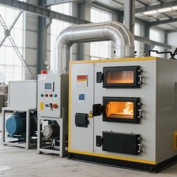
Using a time-of-flight (ToF) laser rangefinder to monitor the combustion bed in a pellet mill is a technical solution that obtains real-time information about the combustion bed's status (such as height, flatness, and material distribution) in a non-contact manner. This can be used to optimize combustion efficiency and prevent problems such as coking or material blockage. The following are the specific implementation ideas, key technical points, and precautions:
The combustion bed of a pellet furnace (such as a biomass pellet furnace) is the zone where fuel (granular biomass) burns, and its state directly affects combustion efficiency.
l Combustion bed height : Too high may lead to insufficient oxygen supply and incomplete combustion; too low may lead to unstable heat output.
l Surface flatness : Local accumulation or depressions may cause local high temperature (coking) or flameout.
l Material consumption rate : Real-time monitoring can be linked to the feeding system to achieve automatic replenishment.
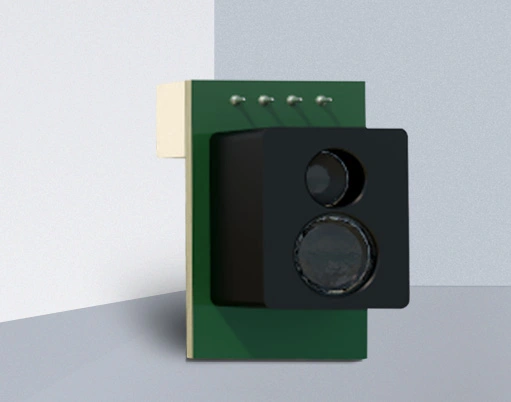
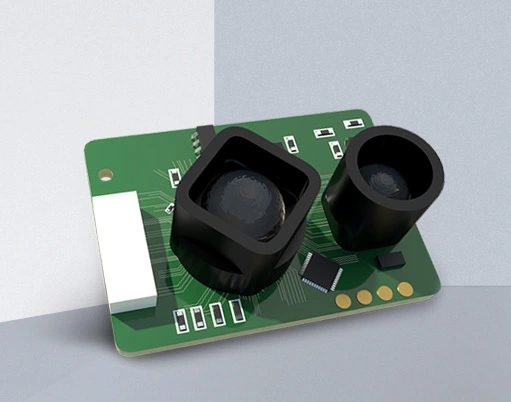
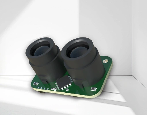
The core function of the ToF sensor is to measure the distance between the combustion bed surface and the sensor in real time , indirectly reflecting the above-mentioned state.
Appropriate sensors need to be selected for the harsh environment of the pellet furnace (high temperature, dust, moisture, vibration):
1. Measurement range:
The installation distance between the combustion bed of the pellet furnace and the sensor is usually 0.3 to 2 meters. A sensor with a measurement range covering 0.1 to 5 meters can be selected (such as VL53L5, TFmini-S, etc.).
2. Accuracy and resolution
need to be differentiated based on the 1~5mm height variation on the surface of the combustion bed. Select a model with an accuracy of ≤±3mm and a resolution of ≥1mm (to avoid measurement fluctuations caused by particle gaps).
3. Anti-interference capability
l Dust resistance : The smoke and dust generated during combustion will scatter the laser. Therefore, it is preferable to select a sensor with a large spot diameter (such as 1 mm or more) or with anti-interference algorithms (such as taking the average of multiple measurements).
l High temperature resistance : The sensor body needs to be kept away from the combustion zone (ambient temperature ≤60℃), or cooled by heat dissipation brackets and cooling air ducts; some industrial-grade sensors (such as the Sick TIM series) can withstand environments of -40~85℃.
l Anti-background light : The strong light from the burning flame may interfere with the receiver. Select a sensor with a narrow-band filter (which only transmits laser wavelengths, such as 940nm infrared).
4. The response speed
is relatively slow (minutes), so a sampling rate of 1~10Hz is sufficient to avoid data redundancy.
5. For output interfaces
, UART (serial port) or I2C interface should be selected first, so as to facilitate connection with microcontrollers (such as Arduino, STM32) or PLCs to realize data transmission and control.
1. Installation location
l The sensor must be directly facing the surface of the combustion bed to avoid tilting, which would cause the measurement distance to be too large (the tilt angle needs to be compensated by geometric correction).
l Keep away from the feed inlet and ash outlet to prevent material splashing or dust from directly covering the sensor lens.
l The lens needs to be fitted with a high-temperature resistant dust cover (such as a quartz glass cover) and cleaned regularly (it can be used with an automatic blowing device).
2. Multi-sensor linkage (optional)
If the combustion bed area is large (such as industrial pellet furnace), a single sensor cannot cover the entire area. Two to three sensors can be installed in different locations to calculate the overall flatness of the combustion bed (such as the highest/lowest difference and average height) through data fusion.
1. Raw data preprocessing
l Filtering outliers: Occasionally sparks or dust clumps during combustion may cause measurement values to jump. Outliers are removed by “median value filtering” or “moving average filtering” (if the deviation of three consecutive measurement values exceeds 10mm, they are discarded).
l Temperature compensation: The measurement accuracy of some sensors (such as VL6180X) is affected by the ambient temperature. It is necessary to collect the ambient temperature through an additional temperature sensor and correct the measured value in the software.
2. State Judgment and Control Logic
l Material replenishment control : When the measured distance exceeds the set threshold for 5 consecutive seconds (e.g., the height of the combustion bed is less than 50mm), the feeding motor is triggered to work until the distance returns to the normal range (e.g., 80~100mm).
l Ash removal reminder : If the height of the combustion bed continues to rise (possibly due to coking or ash accumulation) and exceeds the upper limit threshold (e.g., 150mm), the user will be reminded to remove the ash via a buzzer or APP push notification.
l Combustion optimization : Combined with the fan speed, when the surface flatness deviation of the combustion bed is too large (such as the difference between the highest and lowest points > 30mm), adjust the fan speed distribution to reduce local high temperature.
l ToF sensor: TFmini-S (measuring range 0.1~12m, accuracy ±2cm, serial port output)
l Controller: STM32F103C8T6 (data processing, peripheral control)
l Auxiliary sensor: DS18B20 (ambient temperature monitoring, used for temperature compensation)
l Actuators: Feed motor (stepper motor), dust removal push rod, buzzer
l Power supply: 12V DC power supply (powers the sensors and motors, converted to 3.3V via a DC-DC module for the controller)
1. Sensor initialization: Configure the TFmini-S sampling rate to 5Hz and read distance data via serial port.
2. Data filtering: Take the average of 10 consecutive measurements and filter out abrupt changes in value.
3. Temperature compensation: Based on the temperature value of DS18B20, the preset compensation formula is called (e.g., for every 10°C increase in temperature, the distance correction is +0.5mm).
4. Status judgment:
l If the distance after compensation is greater than 150mm, a dust removal reminder will be triggered.
l If the distance is <50mm → start the feed motor until the distance is ≥80mm.
l Calculate the standard deviation of 5 consecutive measurements. If it is greater than 10 mm, adjust the fan speed.
5. Data upload: Real-time distance and status are sent to the host computer or mobile APP via Bluetooth module (such as HC-05).
1. Lens cleaning : The tar and dust produced by combustion will adhere to the lens, causing measurement failure. It is necessary to wipe it with alcohol wipes regularly, or design an automatic brush cleaning mechanism.
2. Laser safety : Select a Class 1 laser sensor (eye-safe level) to avoid direct exposure to the human body.
3. Vibration resistance : Vibration may occur during the operation of the pellet furnace. The sensor needs to be fixed with a vibration-damping bracket to reduce measurement errors caused by displacement.
4. Calibration : After installation, the actual distance from the sensor to the combustion bed needs to be measured manually and compared with the sensor reading. The deviation should be calibrated by software (e.g., by adding a fixed compensation value).
By monitoring the combustion bed of the pellet furnace using a ToF laser ranging sensor, intelligent control can be achieved, improving combustion efficiency by approximately 10% to 20% while reducing the frequency of manual maintenance. This makes it suitable for upgrading and retrofitting household and small-to-medium-sized industrial pellet furnaces.


 +40729977919
  keysensor.ro@gmail.com


