
In industrial automated production, the integrity of bolt and nut installation directly affects product quality and safety performance. Laser triangulation sensors, with their advantages of non-contact measurement, high precision, and fast response speed, have become an ideal solution for detecting the presence of bolts and nuts. Their core principle is to quickly distinguish between "installed in place" and "missing" states by capturing distance changes on the object's surface, making them widely used in high-precision scenarios such as automotive assembly, machinery manufacturing, and electronic equipment production.
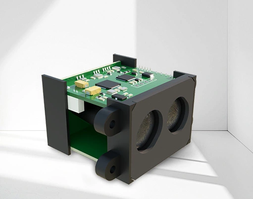
I. Detection Principle: Utilizing Distance Difference for State Recognition. The laser triangulation ranging sensor operates based on an optical triangulation geometric model: a laser beam emitted by the sensor illuminates the surface of the object being measured at a fixed angle. The reflected light is focused by a receiving lens and forms a spot image on a photodetector (CCD/CMOS). When the height of the object changes, the position of the spot on the detector shifts. By calculating the correlation between the shift and distance, the distance between the object's surface and the sensor can be accurately determined. In bolt and nut detection, this distance change becomes the basis for judgment: if the bolt/nut is installed, its head will protrude above the workpiece surface, resulting in a smaller distance value measured by the sensor; if it is missing, the measured position is on the workpiece plane, resulting in a larger distance value. By preset distance thresholds for these two states, the sensor can complete the presence determination within milliseconds. For example, in automotive chassis assembly, if an M10 bolt protrudes 5mm above the panel after installation, the sensor can determine the presence of the bolt by recognizing this 5mm distance difference.
II. Construction of the Detection System: Hardware and Software Co-design
Hardware System Core Sensor Selection: The appropriate sensor model must be selected based on the detection scenario. Recommended measurement range: 5-300mm (covering most industrial bolt installation heights), resolution ≥0.01mm (ensuring the differentiation of minute height differences), sampling frequency ≥1kHz (meeting the high-speed detection requirements of assembly lines). For example, the Keyence LK-G series sensor can achieve a resolution of 0.005mm, suitable for precision detection. Mechanical Positioning Device: The sensor is fixed using a gantry or robotic arm to ensure the laser beam is vertically aligned with the bolt center (deviation ≤0.5mm). For dynamic inspection on assembly lines, a synchronous encoder is required to match the sensor's movement rhythm with the workpiece. Auxiliary Modules: These include a light shield (reducing ambient light interference), an air-blowing cleaning device (preventing dust from adhering to the lens), an industrial-grade PLC (for data processing and logic control), and an alarm device (audio and visual alerts for missing status).
The software algorithm supports a benchmark calibration module: establishing distance benchmarks for "presence" and "missing" locations using standard workpieces. For example, it collects bolt distance values from 100 qualified parts, taking the average as the "presence benchmark" (e.g., 22.5mm); and collects planar distance values from 100 blank parts as the "missing benchmark" (e.g., 27.5mm), setting a tolerance range of ±0.3mm. Filtering and noise reduction: a moving average filtering algorithm (averaging 5 consecutive measurements) is used to eliminate instantaneous errors caused by metal surface reflection or vibration, ensuring data stability. A logical judgment unit: it compares measured values with benchmark thresholds in real time. When the distance falls within the "presence benchmark ±0.3mm" range, it is judged as "presence"; when it falls within the "missing benchmark ±0.3mm" range, it is judged as "missing"; and if it exceeds the range, it is marked as "abnormal" (requiring manual verification). III. Inspection Process: Implementation of the entire process from calibration to online judgment.
Preliminary Calibration and Parameter Setting: Positioning Calibration: Place the workpiece with standard bolts at the inspection station. Manually fine-tune the sensor position to ensure the center of the laser spot coincides with the center of the bolt head (deviation ≤ 0.2mm), ensuring accurate measurement. Reference Value Acquisition: Continuously measure the bolt distance and blank distance of the standard part 50 times. After removing the three maximum and minimum values, take the average and store it in the system as the reference parameter. Threshold Optimization: Adjust the tolerance range according to the bolt specifications. For example, for M6 bolts with small head height deviations, the tolerance is set to ±0.2mm; for large flange nuts, the tolerance can be widened to ±0.5mm.
Online inspection performs workpiece positioning: The workpiece to be inspected is sent to the inspection position via a conveyor belt, and its position is fixed by positioning pins or a vision system (repeatability ≤ 0.1mm), avoiding measurement point deviation due to workpiece offset. Batch inspection: For multi-bolt workpieces (such as engine cylinder blocks), sensors scan each bolt position sequentially according to preset coordinates via a robotic arm, or a multi-sensor array is used to achieve parallel inspection, with the time for a single inspection controlled within 0.5 seconds. Result feedback: Qualified workpieces are released with a green light, while missing workpieces trigger a red light alarm and pause the production line. At the same time, the missing position is marked on the display screen (e.g., "3rd row, 2nd bolt missing"), facilitating quick replacement by workers. IV. Optimization strategy: Technical solutions for complex scenarios
Anti-interference design and reflection suppression: Metal workpiece surfaces are prone to specular reflection, leading to overexposure of the light spot. This can be reduced by adding a polarizer or adjusting the sensor angle (15°-30° to the normal). Environmental adaptability: In high-temperature environments (such as engine hot-end detection), a temperature-resistant sensor (operating temperature -40℃~85℃) should be selected; in dusty environments, the lens should be automatically cleaned with air every hour to avoid a decrease in measurement accuracy.
Accuracy Enhancement Measures: Dynamic Compensation: For the minute deformations caused by vibration in thin workpieces, a planar model is established through multi-point measurements. The distance value of a single bolt is compared with the plane of its surrounding area to eliminate misjudgments caused by overall deformation. Adaptive Threshold: The system automatically calibrates the reference value after inspecting every 1000 workpieces, compensating for sensor drift (typically ≤0.01mm/hour) to ensure long-term inspection accuracy. Laser triangulation sensors provide an efficient solution for bolt and nut presence detection by accurately capturing distance changes. Compared to traditional manual visual or mechanical contact inspection, its inspection efficiency is increased by 5-10 times, with a misjudgment rate of less than 0.1%, significantly reducing quality risks on the production line. With the advancement of Industry 4.0, the integration of this technology with machine vision and the Industrial Internet will enable upgrades to multi-dimensional quality monitoring, from presence detection to installation angle and tightening degree, further promoting the development of intelligent manufacturing.


 +40729977919
  keysensor.ro@gmail.com


